Products
CVM dispensers
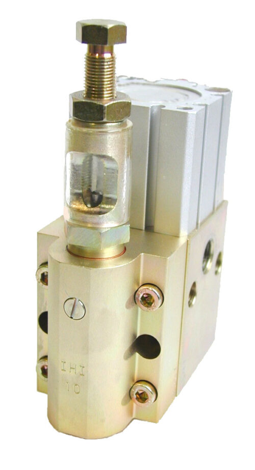
The CVM dispensers are of modular design and are available in 3 different sizes: CVM-03, -10 and -50. As every module has the same width they can be mixed in
one assembly without any limitations. Each assembly can consist of maximum 4 modules and is kept together with 2 tie bolts.
- Description
- Technical info
| Type | CVM-03 | CVM-10 | CVM-50 |
|---|---|---|---|
| Dosage cm³ / slag | 0,05-0,30 | 0,20-1,20 | 0,50-5,0 |
| Minimum fluid line pressure | 5,9 MPa/870 psi | - | - |
| Fluid line operating pressure | 5,9-14,7 MPa/870-2 180 psi | - | - |
| Max fluid line pressure | 20,6 MPa/2 980 psi | - | - |
| Minimum air pressure | 0,3 MPa/43 psi | - | - |
| Air operating pressure | 0,3-0,7 MPa/43-100 psi | - | - |
| Grease | NLGI 0-2 | - | - |
| Weight, kg | 1,4 | 1,5 | 1,6 |
| Part Number: | 907033 | 906504 | 906508 |
| Spare Part Kits | Part Number: |
|---|---|
| To CVM-03 | 907082 |
| To CVM-10 | 907083 |
| To CVM-50 | 907084 |
Operation, CVM dispensers
In the neutral position (Fig. 1) both the air piston and the dispensing piston are in their upper position. Activated (Fig. 2), the large upper area of the air piston is
pressurised, thus connecting the dispensing piston cylinder with the outlet. The pressure of the grease dispensed will now force the dispensing piston downwards (Fig. 3), delivering the amount of material in the cylinder under the dispensing piston. In fig. 4, the lower part of the air piston is pressurised and the upper part is under atmospheric pressure. The piston will then move upwards, sucking back part of the dispensed material.Thanks to this function, a distinct brake of the
material string will occur, thus preventing uncontrolled dripping. Now, the dispensing piston is pressurised on both sides. As the lower area is larger, the piston will move upwards to its upper position defined by the adjusting screw.
Measurements, CVM dosers


| Qty. of dosers | A | B | C | Tie bolt set |
|---|---|---|---|---|
| 2 | 141 | 94 | 82 | Part Number: 907034 |
| 3 | 188 | 141 | 129 | Part Number: 907035 |
| 4 | 235 | 188 | 176 | Part Number: 907036 |
Circuit diagram for CVM
| Type of CVM | H |
|---|---|
| CVM-03 | 104 |
| CVM-10 | 128 |
| CVM-50 | 176 |