Products
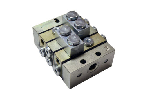
Progressive feeders type PFG and PFM for grease or oil
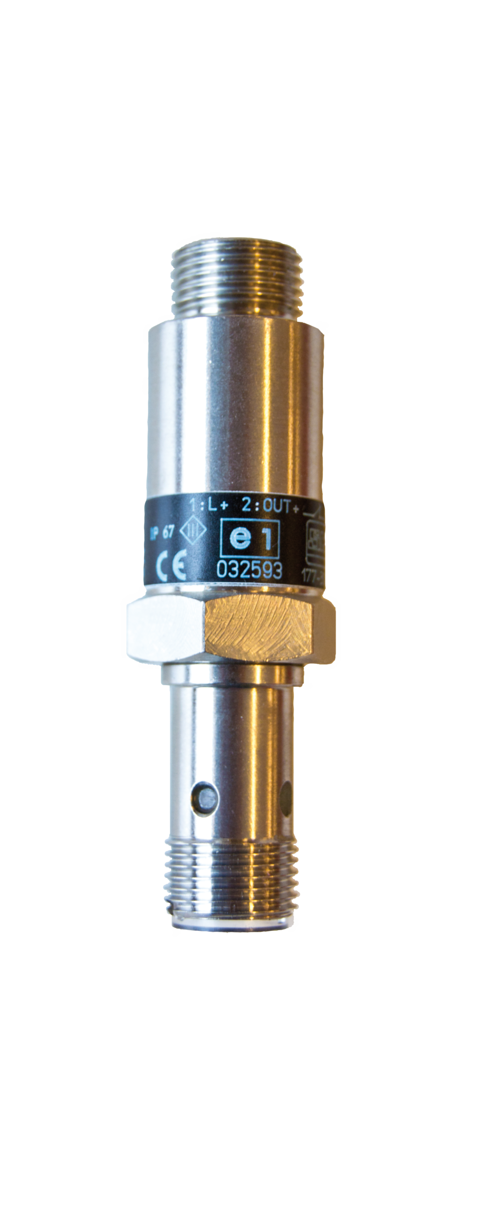
These progressive distributors divide up and distribute the quantity of grease fed to them into portions of equal or unequal amounts which are then discharged to the lubrication points. By this means a single lubricator can serve a large number of application points. The design and operation of the progressive distributor permits simple and reliable control and monitoring of the system operation and lubricant discharged. A complete distributor has a minimum of three dispensing elements, together with inlet and outlet connection. Each metering element has a hydraulically controlled piston which discharges the grease fed to it. The discharged quantity is determined by the diameter and stroke of the piston. Metering elements are available in six different sizes with twelve discharge quantities as tabulated under ”Technical Data”. The pistons of the metering elements operate in a progressive sequence one after the other, which means that each piston cannot make its stroke until the preceding piston has completed its stroke. If any piston is prevented from completing its stroke, the distributor stops immediately and ceases to operate. When all the pistons in a distributor have made a reciprocating movement the feeder has completed a full cycle. The quantity of lubricant (cycle volume) that has to be fed to the distributor is dependent on the number and size of the metering elements, which is governed by the piston diameters and stroke. Monitoring of the piston motion of only one metering element in a distributor enables the whole system to be monitored. A microswitch or inductive transducer energised by the piston sends an electric signal to a control unit or counter for each cycle completed.
- Description
- Technical info
A complete distributor consists of at least 3 dosing elements as well as inlet and end elements. Each metering element has a hydraulically controlled and driven piston that measures and discharges the supplied lubricant. The amount of discharge is determined by the diameter and stroke of the piston. The pistons of the distributor elements work in progressive order one after the other, which means that each piston can make its stroke only after the previous one has completed its. If a piston is prevented from performing its stroke, the distributor stops completely and the lubrication system ceases to function. When all the pistons in a distributor have made a reciprocating movement, the distributor has performed a complete cycle. The amount of fat (cycle volume) that must be added for this depends on the number of elements and their size, i.e. piston diameter and stroke of each element. By monitoring the movement of only one element piston in a distributor, the entire distributor or an entire lubrication system with one or more distributors can be monitored. A microswitch or inductive sensor actuated by the piston provides an electrical signal to a control unit or counter for each completed cycle.
Features
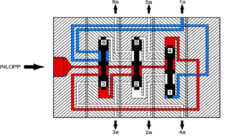
Fig. 1
Due to the pump pressure on the piston end 4, the opposite piston end 1 is forced to discharge grease through outlet 1a. When piston 4/1 has completed its stroke, the cylinder end 4 has been filled with grease and the pump pressure changes to affect the piston end 5.
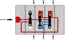
Fig. 2
Piston 5/2 then makes its stroke and the volume of fat below piston head 2 is discharged through outlet 2a. Then piston 6/3 starts and discharges the fat volume below piston end 3 through outlet 3a. The pistons will then move in the opposite direction starting with piston 4/1. A complete cycle has been completed when all pistons have made a reciprocating stroke. In the following cycles, the progressive movement pattern is repeated.
Technical data, progressive distributors PFG and PFM
| Material: | Zink-plated steel |
| Working pressure: | Min 1 MPa, max 20 MPa Min 145 psi, max 2 900 psi |
| Cycles: | Max 200/min (oil) |
Dosage unit sizes:
| Discharge per cycle and outlet | Number of outlets | Title of elements* |
|---|---|---|
| 0.1 cm³ | 2 | 1T |
| 0.2 cm³ | 1 | 1S |
| 0.2 cm³ | 2 | 2T |
| 0.4 cm³ | 1 | 2S |
| 0.3 cm³ | 2 | 3T |
| 0.6 cm³ | 1 | 3S |
| 0.4 cm³ | 2 | 4T |
| 0.8 cm³ | 1 | 4S |
| 0.5 cm³ | 2 | 5T |
| 1.0 cm³ | 1 | 5S |
| 0.6 cm³ | 2 | 6T |
| 1.2 cm³ | 1 | 6S |
*T-element = 2 outlets
S-element = 1 outlet with selectable connection side

